

Support Center
Support Center
Frequently Asked Questions
Case 1: Gimbal power supply is not enough
Answer: Make sure power supply is 3S~6S (12V~24V), make sure the power cable can support 2A electric current.
Case 2: Gimbal internal power problem
Answer: The internal power cable of the gimbal is pressed.
Answer:
(1) The PC needs to install the serial port driver. After connecting USB end to the PC, check the “Device Manager”-”Port”-”USB-SERIAL CH340 (COM x)” to confirm the correct COM port.
(2) If there is no “USB-SERIAL” icon, please install the serial port TTL driver.
(3) After installing the driver, connect the wire TX and RX of the cable together, use the serial port assistant to send data to check whether the serial port environment is normal or not. If it can receive what it just sent to itself, means the cable is normal.
Case 1: Use the provided USB to TTL cable, can control gimbal, but no feedback
Answer: Re-connect both ends of the cable and try again. If there is still no feedback, test the TX-RX of the cable itself (Re. 2.1 How to test the provided USB to TTL cable?). Check if the sent and received data is consistent or not to confirm if the cable is good or not. If the cable is normal, restart the gimbal, and try again. If it is still abnormal, it may be the wiring is an open circuit inside the gimbal. For standard version gimbal, re-connect the 15pin cable on control box. For Viewport version, re-connect the serial port wiring terminal and re-connect the Viewport.
Case 2: Standard version: The yellow jumper cap on the CONN board is off, can not control the gimbal (pitch and yaw), but the camera control (zoom and record) is normal.
A: Need to make short-circuit at the jumper cap position.
Case 3: Standard version: The gimbal is under S.Bus mode, meantime the serial port cannot communicate.
Answer: Follow the related instruction to recover serial port control.
Case 4: Gimbal can not communicate via TCP/TTL.
Answer: Test the gimbal by PWM control. If the camera cannot be controlled, and the program light on the CONN board does not flash, probably the CONN hardware is damaged, return to factory for repair.
Case 5: Standard version: Can control gimbal but not the camera
Answer: 1) Check if the software of the gimbal is match or not, e.g. the cameras (Z40K, Z-Fusion pro, Q30XIR) have 2 baud rates, need to pay attention to this point.
2) Check if the communication from camera RX to CONN board TX is OK or not. If not OK, need to repair.
3) If the communication from camera RX to CONN TX is OK, switch a CONN board of same model (if it’s available) to test, or remove the diode D20 on CONN board and test again.
4) If still not works after all above operations, probably the camera module is broken.
Case 1: The gimbal roll axis hits the yaw motor and rolls randomly or no respond after powering on, or rotate randomly in all 3axis.
Answer:
(1) Connect to serial port, make sure it is well connected
(2) While turning on the camera, continuously send command “3E 1B 00 1B 00 00″ to turn off the motors, keep clicking (or set sending interval 500ms) until motor stop moving.
(3) Send command “3E 45 01 46 0B 0B 3E 1B 00 1B 00 00″, and wait for the automatic calibration of the gimbal to complete
(4) After calibration, adjust the horizontal position of the camera lens align to the installation arrow (you can move manually it to the desired position and wait for 2S), send command “3E 1A 00 1A 00 00″ to save this position (it’s also the home position and the position after power-on self-checking)
Case 2: After powering on, the gimbal pans randomly.
Answer:
(1) The image and data transmitter antenna on the drone interferes with the magnetic encoder of the gimbal. Turn off the transmitter to eliminate the interference and then judge accordingly. If the phenomenon disappears, adjust the position (preferably more 35cm away) or direction (not facing the direction of the gimbal) of the antenna.
(2) Eliminate the interference of the unstable power supply by supplying power to the gimbal independently, or adjusting the voltage (try both 3S and 6S power supply).
(3) Update the program of the CONN board/DJI version software/Viewport controlling software to solve the problem that the serial port is interfered when starting up and incorrectly sent commands. (Solution only for new gimbals that rotate randomly and repeat same issue even temporarily work normal after sending command to calibrate.)
(4) If all the above methods have been tried, the gimbal still rotates after the drone is powered on, indicating that the gimbal is subjected to electromagnetic interference, and the internal data got error, need to send it back to factory for anti-interference processing.
(5) Special case: gimbal rotates after working for a while with CAN, motors are burning hot,
Case 3: After powering on, the gimbal is normal. After a period of time, irregularly jerks or motionless and have a chirping sound
A: Caused by IIC error (The main board controlling chip is broken).
Case 4: Turn off the image & data link and turn on again, the gimbal motor rotates abnormally, and have a chirping sound
Answer: Have you ever disassembled or assembled the damping plate? This operation may cause this problem
Case 5: The gimbal motors not moves but has chirping sound after powering on.
Answer: Send: 3E 3d 00 3d 00 00 to query for the gimbal angle feedback, if all value of IMU are 0, means gimbal IMU abnormal. Check if the 5V output of gimbal control box is normal or not. If normal, check if the internal wiring of IMU is normal or not, or if the connector loose or not. If gimbal is IP only version, check if the slip ring is OK.
Answer: Manual feedback: angle value of each axis, zoom times of the camera, and infrequently used data (tracking offset, rangefinder distance, target position)
Automatic feedback: angle value of each axis and angular velocity (set the feedback mode, turn on the automatic feedback)
The system default automatic feedback structure: (not set the feedback mode)
typedef struct {
uint16_t timestamp
int16_t rollIMUangle
int16_t pitchIMUangle
int16_t yawIMUangle
int16_t rollTAGangle
int16_t pitchTAGangle
int16_t yawTAGangle
int16_t rollTAGspeed
int16_t pitchTAGspeed
int16_t yawTAGspeed
int16_t rollStatorRotorAngle
int16_t pitchStatorRotorAngle
int16_t yawStatorRotorAngle
} T_SbgcGimbalRealtimeDataCustomReq_full
Answer:
follow_yaw_disable (mode not to follow the pan of the drone): 3E 1F 06 25 01 1F 00 00 00 00 20
follow_yaw_enable (mode to follow the pan of the drone): 3E 1F 06 25 01 1F 01 00 00 00 21
query_follow_state (query current mode): 3E 40 02 42 01 1F 20
save gimbal settings (save, the mode of the next startup is the same as the save mode): 3E 20 00 20 00 00
Obtained from the query when starting up: 3E 1F 06 25 01 1F FF FF FF FF 1C (For accurate query, please send the mode command first)
Case 1: Gimbal tracking, after exceeding the limit angle upwards, the gimbal will move downwards. This is normal.
Case 2: Gimbal (old shipment) under speed mode, it cannot be controlled after passing the YAW axis limit.
Case 3: If the gimbal (old shipment) is mounted upside-down and pitch down to the limit, it will cause the lens to face upwards.
1) How gimbal enter the scan mode?
Answer: Add script to gimbal tuning and run the script
Enter scan mode: 3E 45 01 46 1B 1B
Exit scan mode: 3E 45 01 46 1A 1A
2) Gimbal receive stop feedback
Answer: send command “AA 55 20 10 FF”, then turn on to enable.
Send: FF 01 0F 10 00 00 00 00 00 00 00 00 00 00 00 00 00 00 00 00
Receive: 3E 43 01 44 43 43
3) Gimbal goes over the target under tracking mode.
Answer: Send command: AA 55 28 50 FF AA 55 2B 50 FF
Case 1: Modify pitch/yaw angle control range by RC Control
Answer:
(1) Send command: 3E 15 00 15 00 00
(2) Get the feedback value
(3) After changing the corresponding bit, send the changed command to the gimbal (CS: Sum from 5th byte to last byte modulo 256)
For example: send: 3E 15 00 15 00 00
Feedback:3E 15 86 9B 00 64 0A 46 50 01 0E 64 0A 46 5A 00 0E 64 0A 46 6E 00 0E 64 00 00 D3 FF 2D 00 01 03 14 00 D3 FF 5A 00 01 03 1E 00 30 FD D0 02 01 03 1E 01 3C 00 01 00 00 00 00 37 0A 00 00 02 04 00 00 00 00 00 00 32 32 00 00 00 03 02 03 01 00 02 00 01 02 00 00 00 26 11 18 19 1B 00 07 04 03 C8 FB 22 FC 14 FB 8B 28 14 00 00 00 1E 1E 3C 00 00 00 00 00 00 00 00 00 00 00 05 07 0F 32 06 03 03 03 53 07 50 04 00 00 00 01 00 0B
Analysis on the feedback:
[
Frame header:3E 15 86 9B
Data body:
00 64 0A 46 50 01 0E 64 0A 46 5A 00 0E 64 0A 46 6E 00 0E 64 00 00 D3 FF 2D 00 01 03 14 00 D3 FF 5A 00 01 03 1E 00 30 FD D0 02 01 03 1E 01 3C 00 01 00 00 00 00 37 0A 00 00 02 04 00 00 00 00 00 00 32 32 00 00 00 03 02 03 01 00 02 00 01 02 00 00 00 26 11 18 19 1B 00 07 04 03 C8 FB 22 FC 14 FB 8B 28 14 00 00 00 1E 1E 3C 00 00 00 00 00 00 00 00 00 00 00 05 07 0F 32 06 03 03 03 53 07 50 04 00 00 00 01 00
Checksum:0B (Sum of each byte of the data body modulo 256)
]
In data body
(D3 FF 5A 00–>0xFFD3=-45 Pitch up 45° 0x005A=90° pitch down 90°, Up negative down positive)
(30 FD D0 02–>0xFD30=-720 Yaw left 720° 0x02D0=right720° Yaw right 720°, left negative right positive)
Write the modify value:
3E 16 86 9C 00 64 0A 46 50 01 0E 64 0A 46 5A 00 0E 64 0A 46 6E 00 0E 64 00 00 D3 FF 2D 00 01 03 14 00 xx xx xx xx 01 03 1E 00 xx xx xx xx 01 03 1E 01 3C 00 01 00 00 00 00 37 0A 00 00 02 04 00 00 00 00 00 00 32 32 00 00 00 03 02 03 01 00 02 00 01 02 00 00 00 26 11 18 19 1B 00 07 04 03 C8 FB 22 FC 14 FB 8B 28 14 00 00 00 1E 1E 3C 00 00 00 00 00 00 00 00 00 00 00 05 07 0F 32 06 03 03 03 53 07 50 04 00 00 00 01 00 CS
Case 2: Yaw encoder angle value setting
Answer:
Send:3E 3E 00 3E 00
Feedback:3E 3E 97 D5 00 00 01 9A 00 00 00 00 00 00 00 00 00 00 00 00 00 00 00 00 00 00 00 64 64 64 5F 5F 5F 14 00 00 00 00 00 00 DE FE 00 00 00 00 22 01 87 00 78 3C 00 00 00 00 00 00 58 02 88 13 32 00 00 00 00 00 00 32 32 32 14 14 14 3C 3C 3C 00 00 00 00 00 00 00 00 00 00 00 00 00 00 00 00 00 00 00 00 00 00 00 00 00 00 00 00 00 00 00 00 00 00 00 00 00 00 00 00 00 00 00 00 00 00 00 00 00 00 00 00 00 00 00 00 00 00 00 00 00 00 00 00 00 00 00 00 02 00 00 00 00 00 00 00 00 E1
Analyse:
00 00:roll
00 00:pitch
DE FE:yaw 0xFEDE–>-290
22 01:yaw 0×0122–> 290
Write the modify value:
Send: 3E 3F 97 D6 00 00 01 9A 00 00 00 00 00 00 00 00 00 00 00 00 00 00 00 00 00 00 00 64 64 64 5F 5F 5F 14 00 00 00 00 00 00 DE FE 00 00 00 00 22 01 87 00 78 3C 00 00 00 00 00 00 58 02 88 13 32 00 00 00 00 00 00 32 32 32 14 14 14 3C 3C 3C 00 00 00 00 00 00 00 00 00 00 00 00 00 00 00 00 00 00 00 00 00 00 00 00 00 00 00 00 00 00 00 00 00 00 00 00 00 00 00 00 00 00 00 00 00 00 00 00 00 00 00 00 00 00 00 00 00 00 00 00 00 00 00 00 00 00 00 00 02 00 00 00 00 00 00 00 00 E1
Case 3: Gimbal yaw does not follow or follow is too much sensitive.
Answer:
(1) Use the Mode channel of the remote control to switch quickly 4 times in a row (three-gear switch: middle gear –> high gear –> medium gear –> high gear –> medium gear –> high gear - -> Middle gear –> High gear) to see if it follows or not.
(2) Use Viewlink control software, serial port control, turn on “Enable Follow” to see if it follows or not.
(3) Use the command to query the parameters, after getting the feedback parameters, modify the corresponding parameters. Save the setting by sending: 3E 20 00 20 00.
Send: 3E 15 00 15 00 00
Feedback:3E 15 86 9B 00 64 0A 46 82 01 0E 64 0A 46 64 00 0E 64 0A 46 A0 00 0E 64 00 00 D3 FF 2D 00 01 03 14 00 D3 FF 5A 00 01 03 13 00 D4 FE 2C 01 01 03 13 01 3C 00 01 00 00 00 00 37 0A 00 00 02 04 03 00 00 00 00 00 32 32 00 00 00 FD FF 03 01 00 02 00 01 02 00 00 17 12 11 18 19 00 00 07 04 03 C8 FB 22 FC 14 FB 8B 28 14 00 00 00 1E 1E 3C 00 00 00 00 00 00 00 00 00 00 00 05 07 0F 32 06 03 03 03 51 07 10 44 00 00 00 01 00 43
32 : dead-band (increase this value to reduce the follow sensitivity)
32 : expo curve
1E 1E 3C: Follow SPEED
03 03 03: Follow LPF
Send:
3E 16 86 9C 00 64 0A 46 82 01 0E 64 0A 46 64 00 0E 64 0A 46 A0 00 0E 64 00 00 D3 FF 2D 00 01 03 14 00 D3 FF 5A 00 01 03 13 00 D4 FE 2C 01 01 03 13 01 3C 00 01 00 00 00 00 37 0A 00 00 02 04 03 00 00 00 00 00 64 3C 00 00 00 FD FF 03 01 00 02 00 01 02 00 00 17 12 11 18 19 00 00 07 04 03 C8 FB 22 FC 14 FB 8B 28 14 00 00 00 1E 1E 3C 00 00 00 00 00 00 00 00 00 00 00 05 07 0F 32 06 03 03 03 51 07 10 44 00 00 00 01 00 CS
Send: 3E 3E 00 3E 00 00
Feedback: 3E 3E 97 D5 00 00 01 9A 00 00 00 00 00 00 00 00 00 00 00 00 00 00 00 00 00 00 00 64 64 64 5F 5F 5F 14 00 00 00 00 00 00 DE FE 00 00 00 00 22 01 87 00 78 3C 00 00 00 00 00 00 58 02 88 13 32 00 00 00 00 00 00 32 32 32 14 14 14 3C 3C 3C 00 00 00 00 00 00 00 00 00 00 00 00 00 00 00 00 00 00 00 00 00 00 00 00 00 00 00 00 00 00 00 00 00 00 00 00 00 00 00 00 00 00 00 00 00 00 00 00 00 00 00 00 00 00 00 00 00 00 00 00 00 00 00 00 00 00 00 00 02 00 00 00 00 00 00 00 00 E1
3C 3C 3C: Follow RANGE
For example, send modification command: 3E 3F 97 D6 00 00 01 9A 00 00 00 00 00 00 00 00 00 00 00 00 00 00 00 00 00 00 00 64 64 64 5F 5F 5F 14 00 00 00 00 00 00 DE FE 00 00 00 00 22 01 87 00 78 3C 00 00 00 00 00 00 58 02 88 13 32 00 00 00 00 00 00 32 32 32 14 14 14 01 01 3C 00 00 00 00 00 00 00 00 00 00 00 00 00 00 00 00 00 00 00 00 00 00 00 00 00 00 00 00 00 00 00 00 00 00 00 00 00 00 00 00 00 00 00 00 00 00 00 00 00 00 00 00 00 00 00 00 00 00 00 00 00 00 00 00 00 00 00 00 02 00 00 00 00 00 00 00 00 CS
Case 4: Q: How to set gimbal pitch initial angle?
Answer:
(1) Send:3E 15 00 15 00 00 00
(2) Receive:3E 15 86 9B 00 64 0A 46 A0 01 0E 64 0A 46 8C 00 0E 64 0A 46 B4 00 0E 64 00 00 D3 FF 2D 00 01 03 14 00 D3 FF 5A 00 01 03 0B 00 D4 FE 2C 01 01 03 0B 01 3C 00 01 00 00 00 00 37 0A 00 00 02 04 03 00 00 00 00 00 32 32 00 00 00 01 03 FD FF 00 02 00 01 02 00 00 17 12 11 18 19 00 00 07 04 03 C8 FB 22 FC 14 FB 8B 28 14 00 00 00 1E 1E 1E 00 00 00 00 00 00 00 00 00 00 00 05 07 0F 32 06 03 03 03 51 07 10 44 00 00 00 01 00 6F
00 00: pitch initial angle is 0°
(3) If want to set pitch 45°,0×0800–> 2048 –>2048×0.02197265625=45
Send:3E 16 86 9C 00 64 0A 46 A0 01 0E 64 0A 46 8C 00 0E 64 0A 46 B4 00 0E 64 00 00 D3 FF 2D 00 01 03 14 00 D3 FF 5A 00 01 03 0B 00 D4 FE 2C 01 01 03 0B 01 3C 00 01 00 00 00 00 37 0A 00 00 02 04 03 00 00 00 00 00 32 32 00 00 00 01 03 FD FF 00 02 00 01 02 00 00 17 12 11 18 19 00 00 07 04 03 C8 FB 22 FC 14 FB 8B 28 14 00 00 00 1E 1E 1E 00 00 00 00 08 00 00 00 00 00 00 05 07 0F 32 06 03 03 03 51 07 10 44 00 00 00 01 00 77
(4) Send: 3E 20 00 20 00 to save the setting.
Case 5: Q: How to switch gimbal PWM speed mode/ angle mode?
Answer:
(1) First send: 3E 15 00 15 00 00
(2) Get the return value
(3) After changing the corresponding bit, send the changed instruction to the gimbal (checksum: sum of all bits from 6th byte to the last byte modulo 256)
Such as: send: 3E 15 00 15 00 00
Receive:3E 15 86 9B 00 64 0A 46 50 01 0E 64 0A 46 5A 00 0E 64 0A 46 6E 00 0E 64 00 00 D3 FF 2D 00 01 03 14 00 D3 FF 5A 00 01 03 1E 00 30 FD D0 02 01 03 1E 01 3C 00 01 00 00 00 00 37 0A 00 00 02 04 00 00 00 00 00 00 32 32 00 00 00 03 02 03 01 00 02 00 01 02 00 00 00 26 11 18 19 1B 00 07 04 03 C8 FB 22 FC 14 FB 8B 28 14 00 00 00 1E 1E 3C 00 00 00 00 00 00 00 00 00 00 00 05 07 0F 32 06 03 03 03 53 07 50 04 00 00 00 01 00 0B
Analysis of received instructions:
01:speed mode –>changed to 02:angle mode
37:RC_DEADBAND –>changed to 00
0A:RC_EXPO_RATE –>changed to 00
Write the modify value:
Send:3E 16 86 9C 00 64 0A 46 50 01 0E 64 0A 46 5A 00 0E 64 0A 46 6E 00 0E 64 00 00 D3 FF 2D 00 02 03 14 00 D3 FF 5A 00 02 03 1E 00 30 FD D0 02 02 03 1E 01 3C 00 01 00 00 00 00 00 00 00 00 02 04 00 00 00 00 00 00 32 32 00 00 00 03 02 03 01 00 02 00 01 02 00 00 00 26 11 18 19 1B 00 07 04 03 C8 FB 22 FC 14 FB 8B 28 14 00 00 00 1E 1E 3C 00 00 00 00 00 00 00 00 00 00 00 05 07 0F 32 06 03 03 03 53 07 50 04 00 00 00 01 00 CD
Case 6: Q: How to modify the power value of gimbal motor?
Answer:
(1) Get the PID parameters of gimbal roll, pitch and yaw
Send: 3E 40 04 44 03 09 0A 0B 21
Feedback example: (POWER_ROLL=75, POWER_PITCH=75, POWER_YAW=115)
3E 1F 10 2F 03 09 4b 00 00 00 0a 4b 00 00 00 0b 73 00 00 00 2a
Frame header:3E 1F 10 2F
Data body:03 09 4b 00 00 00 0a 4b 00 00 00 0b 73 00 00 00
Checksum: 2a
|
Parameter NAME
|
ID
|
TYPE
|
MIN
|
MAX
|
|
POWER_ROLL |
9 |
1u |
0 |
255 |
|
POWER_PITCH |
10 |
|||
|
POWER_YAW |
11 |
(2) Set the motor value of roll, pitch and yaw
(POWER_ROLL=75, POWER_PITCH=100, POWER_YAW=115)
Such as send:3E 1f 10 2F 03 09 4b 00 00 00 0a 64 00 00 00 0b 73 00 00 00 43 (The last bit is sum of red bits modulo 256)
(3)Save the settings from the previous step
send:3E 20 00 20 00
Case 7: Q: How to modify the PID parameters of gimbal motor?
Answer:
(1) Get the gimbal roll, pitch, yaw PID parameters
Send: 3E 40 0A 4A 09 00 01 02 06 07 08 2A 2B 2C A2
Feedback example:
3E 1F 2E 4D
09
00 64 00 00 00———-ROLL P= 100
01 64 00 00 00———-PITCH P=100
02 78 00 00 00———YAW P=120
06 46 00 00 00 ———R D= 70
07 46 00 00 00———P D=70
08 64 00 00 00———Y D=70
2A 5F 00 00 00———R G=2
2B 5F 00 00 00———P G=2
2C 5F 00 00 00———Y G=2
EF—- checksum = LSB of all blue bytes
GAIN = 0.1 + X * 0.02 X=50*gain -5 2 = 0.1 + 95* 0.02
(2) Write the modification command
Such as send: 3E 1F 2E 4D 09 00 64 00 00 00 01 64 00 00 00 02 78 00 00 00 06 46 00 00 00 07 46 00 00 00 08 64 00 00 00 2A 5F 00 00 00 2B 5F 00 00 00 2C 5F 00 00 00 EF
(3) Save the settings of the 2nd step
Send: 3E 20 00 20 00
Case 8: Q: How to query and modify encoder value?
Answer:
(1) Send: 3E 21 00 21 00 00 to get value
(2) Write modified value
(3) Send: 3E 20 00 20 00 to save setting.
Example:
Send: 3E 21 00 21 00 00
Receive: 3E 21 68 89 00 23 23 37 1E 14 14 00 0C 3B 00 04 05 00 1D 1F 00 02 05 00 00 00 00 00 00 00 00 00 B6 C8 B0 20 34 FD 54 02 71 F9 1A 03 00 C8 C8 00 00 00 00 00 00 00 00 32 00 00 00 00 01 00 01 00 01 00 00 00 00 00 00 14 14 14 00 FB F6 64 FE 14 28 0D 04 0E 04 E4 03 0B 08 0D 07 07 00 32 32 32 00 00 00 03 01 32 00 14 00 14 14 14 96
54 02: 0×0254 Roll encoder value
71 F9: 0xF971 Pith encoder value
1A 03: 0x031A Yaw encoder value
B6 C8: 0xC8B6 Roll home position
B0 20: 0x20B0 Pitch home position
34 FD: 0xFD34 Yaw home position
Write the corresponding command:
Send: 3E 22 68 8A 00 23 23 37 1E 14 14 00 0C 3B 00 04 05 00 1D 1F 00 02 05 00 00 00 00 00 00 00 00 00 B6 C8 B0 20 34 FD 54 02 71 F9 21 03 00 C8 C8 00 00 00 00 00 00 00 00 32 00 00 00 00 01 00 01 00 01 00 00 00 00 00 00 14 14 14 00 FB F6 64 FE 14 28 0D 04 0E 04 E4 03 0B 08 0D 07 07 00 32 32 32 00 00 00 03 01 32 00 14 00 14 14 14 9D
Answer:
(1) Check the stability of the gimbal when powered off, ensure the balance of each axis.
(2) Check the mounting method, the type of damping balls, whether they are too less or too many, whether they are aged, and whether the damping plate has been modified.
(3) Check whether the external wiring of the gimbal is pulled tightly to the gimbal.
(4) Modify the gimbal PID parameters.
Case 1: Some frame header “AA…” / ”55 AA…” / “7E 7E…” not in gimbal protocol file are sent which caused analysis error and gimbal no respond.
Answer: Change the frame header of non gimbal protocol, could not be similar.
Case 2: Some invalid data are sent via serial port to the gimbal cause the gimbal serial port no respond.
Answer: Modify software: Reduce serial port voltage when power on, or delay the startup of the serial port.
It is a temperature alarm, which can be eliminated
Case 1: Use Viewlink software, PWM, S.BUS control
Answer:
(1) Connect serial port, make sure it is well connected.
(2) Send commands “AA 55 0A 96 FF” and “AA 55 0B 43 FF”, and the received feedback commands are same as sent.
Case 2: Use protocol control
Answer: Picture-in-picture switching/color palette switching command, which needs to set the temperature alarm value; the 9th to 12th byte in the 7E command is the temperature measurement alarm setting bytes, float single-precision floating-point 32-bit (4 bytes, big- endian) is converted into a decimal temperature value, the factory default value is 300° (float: 43 96 00 00)
For example:
EO+IR thermal (Fusion pseudo color):
7E 7E 44 00 00 78 00 00 00 00 96 43 01 00 00 00 00 01 01 00 00 00 00 00 00 00 00 00 00 00 00 00 00 00 00 00 00 00 00 00 00 00 00 00 00 00 00 94
IR thermal (Fusion pseudo color):
7E 7E 44 00 00 78 00 00 00 00 96 43 01 00 01 00 00 01 01 00 00 00 00 00 00 00 00 00 00 00 00 00 00 00 00 00 00 00 00 00 00 00 00 00 00 00 00 95
IR thermal (Fusion pseudo color) + EO:
7E 7E 44 00 00 78 00 00 00 00 96 43 01 00 02 00 00 01 01 00 00 00 00 00 00 00 00 00 00 00 00 00 00 00 00 00 00 00 00 00 00 00 00 00 00 00 00 96
EO only:
7E 7E 44 00 00 78 00 00 00 00 96 43 01 00 03 00 00 01 01 00 00 00 00 00 00 00 00 00 00 00 00 00 00 00 00 00 00 00 00 00 00 00 00 00 00 00 00 97
EO+IR thermal (white hot):
7E 7E 44 00 00 78 00 00 00 00 96 43 00 00 00 00 00 01 01 00 00 00 00 00 00 00 00 00 00 00 00 00 00 00 00 00 00 00 00 00 00 00 00 00 00 00 00 93
IR thermal only (white hot):
7E 7E 44 00 00 78 00 00 00 00 96 43 00 00 01 00 00 01 01 00 00 00 00 00 00 00 00 00 00 00 00 00 00 00 00 00 00 00 00 00 00 00 00 00 00 00 00 94
IR thermal (white hot)+ EO:
7E 7E 44 00 00 78 00 00 00 00 96 43 00 00 02 00 00 01 01 00 00 00 00 00 00 00 00 00 00 00 00 00 00 00 00 00 00 00 00 00 00 00 00 00 00 00 00 95
EO only:
7E 7E 44 00 00 78 00 00 00 00 96 43 00 00 03 00 00 01 01 00 00 00 00 00 00 00 00 00 00 00 00 00 00 00 00 00 00 00 00 00 00 00 00 00 00 00 00 96
EO+IR thermal (black hot):
7E 7E 44 00 00 78 00 00 00 00 96 43 00 00 00 01 00 01 01 00 00 00 00 00 00 00 00 00 00 00 00 00 00 00 00 00 00 00 00 00 00 00 00 00 00 00 00 94
IR thermal only (black hot):
7E 7E 44 00 00 78 00 00 00 00 96 43 00 00 01 01 00 01 01 00 00 00 00 00 00 00 00 00 00 00 00 00 00 00 00 00 00 00 00 00 00 00 00 00 00 00 00 95
IR thermal (black hot) + EO:
7E 7E 44 00 00 78 00 00 00 00 96 43 00 00 02 01 00 01 01 00 00 00 00 00 00 00 00 00 00 00 00 00 00 00 00 00 00 00 00 00 00 00 00 00 00 00 00 96
EO only:
7E 7E 44 00 00 78 00 00 00 00 96 43 00 00 03 01 00 01 01 00 00 00 00 00 00 00 00 00 00 00 00 00 00 00 00 00 00 00 00 00 00 00 00 00 00 00 00 97
Case 1: The gimbal is mounted normally (hanging), the EO picture is normal, but the thermal image is inverted
Answer: Connect serial port and make sure the communication is normal. Send the thermal image upright command: “7e 7e 44 00 00 91 80 00 00 00 00 00 00 00 00 00 00 00 00 00 00 00 00 00 00 00 00 00 00 00 00 00 00 00 00 00 00 00 00 00 00 00 00 00 00 00 00 00 51″, the thermal image will be normal.
Expand:
Thermal image upside down: “7e 7e 44 00 00 91 c0 00 00 00 00 00 00 00 00 00 00 00 00 00 00 00 00 00 00 00 00 00 00 00 00 00 00 00 00 00 00 00 00 00 00 00 00 00 00 00 00 00 91″
EO camera: (Image forward rotation: 81 01 04 66 03, FF Image reverse: 81 01 04 66 02 FF, Reverse setting save: 81 01 04 3F 01 7F FF)
Case 1: Need to select a specific image as the startup screen
Answer: Send the serial command “Type+Save”
EO + IR (white hot): “7e 7e 44 00 00 78 00 00 00 00 96 43 00 00 00 00 00 00 00 00 00 00 00 00 00 00 00 00 00 00 00 00 00 00 00 00 00 00 00 00 00 00 00 00 00 00 00 91″
EO + IR (black hot): “7e 7e 44 00 00 78 00 00 00 00 96 43 00 00 00 01 00 00 00 00 00 00 00 00 00 00 00 00 00 00 00 00 00 00 00 00 00 00 00 00 00 00 00 00 00 00 00 92″
IR (white hot): “7e 7e 44 00 00 78 00 00 00 00 96 43 00 00 01 00 00 00 00 00 00 00 00 00 00 00 00 00 00 00 00 00 00 00 00 00 00 00 00 00 00 00 00 00 00 00 00 92″
IR only (white hot) + EO: “7e 7e 44 00 00 78 00 00 00 00 96 43 00 00 02 02 00 00 00 00 00 00 00 00 00 00 00 00 00 00 00 00 00 00 00 00 00 00 00 00 00 00 00 00 00 00 00 95″
EO only: “7e 7e 44 00 00 78 00 00 00 00 96 43 00 00 03 02 00 00 00 00 00 00 00 00 00 00 00 00 00 00 00 00 00 00 00 00 00 00 00 00 00 00 00 00 00 00 00 96″
Save: “7e 7e 44 00 00 8e 00 00 00 00 00 00 00 00 00 00 00 00 00 00 00 00 00 00 00 00 00 00 00 00 00 00 00 00 00 00 00 00 00 00 00 00 00 00 00 00 00 ce”
Case 1: Connect serial port, send serial port command
Answer: Send serial command “7e 7e 44 00 00 d4 00 00 00 00 00 00 00 00 00 00 00 00 00 00 00 00 00 00 00 00 00 00 00 00 00 00 00 00 00 00 00 00 00 00 00 00 00 00 00 00 00 14”. If there is video output, the software version information will appear in the lower left corner of the screen in 2 lines. (as below shown)
Case 2:Connect TCP, send TCP command
Answer: Send TCP command ”EB 90 30 7E 7E 44 00 00 D4 00 00 00 00 00 00 00 00 00 00 00 00 00 00 00 00 00 00 00 00 00 00 00 00 00 00 00 00 00 00 00 00 00 00 00 00 00 00 00 00 00 14 28”. If there is video output, the software version information will appear in the lower left corner of the screen in 2 lines. (as below shown)
Case 3: After powering on, immediately turn on the video stream (HDMI or IP) and wait for the version information display automatically which will disappear in 30 seconds.
Case 4: If there is no video stream output or abnormal, connect IP output by configuration tool (download from Viewpro website) and click Search Version at bottom and the version number will be display in the box.
Case 1: The power is cut off without stopping the record, causing the stored video file damaged
Answer:
1. H264 format, the video can be played without stopping record when the power is interrupted
2.Set by protocol to pack the videos by segments.
3.Recover video files by repairing software
Answer: Use track size cmd to set the desired size. Sent once, this size will be stored in eeprom: AA 55 1E SZ FF, please note that SZ is hexadecimal
0×24: Small template 32
0×28: Medium template 64
0×30: Large template 128
The above information can be superimposed, for example:
0x2c: small template + medium template
0×38: Medium template + large template
Example: You can send AA 55 1E 28 FF to set the track size to a medium template
Answer:
Send command: AA 55 20 02 FF —— output offset
AA 55 20 00 FF —— don’t output offset
Output format: BB 01 XL XH YLYH 02 CS (CS: sum of all bytes modulo 256)
For example: BB 01 2A 01 80 FE 42 A7
X-axis offset 0x012A–> 298 Y-axis offset 0xFE80–> -384 (relative to the center point deviation pixel point: right positive, left negative, bottom positive, above negative)
When sending stop tracking command, it will feedback: BB 01 00 00 00 00 20 DC

Viewlink Protocol: the center point is 0, the center coordinate of offset (0,0)
Subtract (960, 540) from the pixel coordinates of the locked targets
| 1 | Frame Header | 0xBB | |
| 2 | Address | 0×01 | |
| 3 | X-axis offset | LSB | |
| 4 | FSB | ||
| 5 | Y-axis offset | LSB | |
| 6 | FSB | ||
| 7 | Status | BYTE0 0: Don’t display tracking box1: Display tracking boxBYTE1 0: No target
1: Tracking target BYTE2 0: EO 1: IR BYTE3 0: Single image display 1: PIP display BYTE4 0: Within preset temperature 1: exceed preset temperature BYTE56 Secondary tracking change status in circle, 3 status in total: 1, 2, 3 BYTE 7 Reserved |
|
| 8 | Checksum |
Pointing tracking points (960, 540):
(1) 7E 7E 44 00 00 86 00 C0 03 1C 02 00 01 3C 00 00 00 00 00 00 00 00 00 00 00 00 00 00 00 00 00 00 00 00 00 00 00 00 00 00 00 00 00 00 00 00 00 E4
(2) 55 AA DC 0D 31 00 00 00 00 00 0A 00 00 00 00 36
Answer: For example, red hot alarm
7E 7E 44 00 00 78 00 00 00 00 00 30 00 00 01 82 00 00 00 00 00 00 00 00 00 00 00 00 00 00 00 00 00 00 00 00 00 00 00 00 00 00 00 00 00 00 00 6B
Answer:
Modify the IP settings of the Ethernet output version gimbal:
IP:192.168.0.2 7e 7e 44 00 00 87 c0 a8 00 02 00 00 00 00 00 00 00 00 00 00 00 00 00 00 00 00 00 00 00 00 00 00 00 00 00 00 00 00 00 00 00 00 00 00 00 00 00 31
IP:192.168.0.3 7e 7e 44 00 00 87 c0 a8 00 03 00 00 00 00 00 00 00 00 00 00 00 00 00 00 00 00 00 00 00 00 00 00 00 00 00 00 00 00 00 00 00 00 00 00 00 00 00 32
IP:192.168.1.160 7e 7e 44 00 00 87 c0 a8 01 A0 00 00 00 00 00 00 00 00 00 00 00 00 00 00 00 00 00 00 00 00 00 00 00 00 00 00 00 00 00 00 00 00 00 00 00 00 00 D0
Answer:
1.Format a TF card
2.Create a file in the TF card and name it as “update” , and put the software ”S303M32 .bin” into this file.
3.Insert the TF card into the camera
4.Power on the camera
5.Wait for 2 ~3minutes (Screen will indicate the success if there is video output. The gimbal will have home position indication sound after upgrade finished.)
6.Restart the camera

Case 1: The computer Ethernet connection shows network connection error

Answer: The gimbal Ethrenet interface is not connected or connection is not well, reconnect it. If it’s still abnormal, use a multimeter to measure the resistance of 4 Ethernet wires of the gimbal. Measure the resistance of any each 2 wires, between 3-4Ω is normal, if not, the gimbal’s failure.
Case 2: The gimbal IP address can ping well, and the Viewlink TCP control can be connected
Answer:
A. Reconfigure the encode settings with the Camera Configuration Tool (download from Viewpro website) according to factory default settings, and restart the gimbal. DHCP needs to be turned off when output video by RTSP.
B. Viewlink can control gimbal via TCP, but can’t output video stream. And video stream works well in other playback software, then turn off all the firewalls of your computer.
Case 3: The computer Ethernet connection shows that the network connection is normal, but the gimbal IP address cannot ping normally (If you ever changed the IP)
Answer: Use a USB to TTL cable, connect the computer to the gimbal serial port, open Viewlink -> “settings” -> “extended commands”, and send: “7E 7E 44 00 00 87 C0 A8 02 77 00 00 00 00 00 00 00 00 00 00 00 00 00 00 00 00 00 00 00 00 00 00 00 00 00 00 00 00 00 00 00 00 00 00 00 00 00 00 00 A8 “, restore the factory default IP (rtsp://192.168.2.119/554), Restart the gimbal and connect again.
Case 4: Gimbal IP address cannot ping (and Case 2 B processing can not help, because the coding parameters are incorrect)
Answer: Use the TF card to upgrade the IP firmware to recover the IP and encoding settings. Restart after the upgrade.
Case 1: Both serial port (TTL) and TCP control cannot be connected, video stream is normal (Viewport version)
Answer: Press on the Reset button on the control box of Viewport and hold until upgrade finished. Power on the gimbal. Upgrade on Viewlink: “Settings” -> “firmware upgrade” -> “upgrade file” -> “start”, re-burn the program, restart the gimbal and try the control again.
Case 2: The serial port is normal, but TCP can not connect, video stream is normal
Answer:
(1) The computer has turned on VPN or firewalls. Please turn of VPN and firewalls.
(2) The serial port TX of camera is broken. Check OSD zoom changes or not or tracking works or not by serial port control. If OSD no change when zoom or could not start tracking means TX of camera is broken.
(3) Some gimbals not support TCP control. Please refer to the product specification or manual for details.
Case 1: Use Viewpro USB to TTL cable, the software can control gimbal, but upgrade timeout
Answer: USB to TTL cable may be not well connected, reconnect both ends.
Case 2: The upgrade is interrupted during the upgrade process, and the serial port can no longer be connected.
Answer: Use the old method to upgrade by SecureCRT
Case 1: The gimbal is with very old CONN board (chipset is not 303, or purchased before 20190715)
Answer: Not support S.Bus control.
Case 2: The gimbal is a new CONN board (blue CONN version)
Answer:
1. Check whether the wiring is correct
2. Reset S.Bus control
3. Test the S.Bus function. If only half functions are supported, upgrade the CONN board to the latest software.
Case 3: After setting the S.bus channels in the gimbal, only one side works.
Answer: The gimbal during 20190715–20200515 needs to upgrade the CONN board program and use the latest S.Bus setting method to solve the problem.
Case 1: The IP of the Z10N/Q30N/Q30XIR cannot be found
Answer: Power on the gimbal and connect directly to the computer. Set to obtain network automatically. Use “wireshark” to capture the network data, and use the filter to enter “arp” to find the IP.
Case 2: Can not find the IP of T series gimbal?
Answer:
(1) Create a folder in the root directory of the TF card and name it as “update”.
(2) Put the compressed package of up.tar.xz (or up.tar) directly into the update folder.
(3) Insert the TF card into the card slot of camera when the it is powered off.
(4) Power on the gimbal
(5) Wait 2 minutes, power off and take out the TF card
(6) Restart the gimbal and the upgrade is finished.
Case 1: After the stream is pushed by video transmitter, the image of the gimbal is blurred when moving
Answer: The video transmitter bit rate is too low. (Min 1M 720p)
Case 2: Z40K IP output version will get black when switching modes.
Answer: Set the output resolution of the camera to HDMI 1080i.
Case 3: T series through LB2 video transmitter.
Answer: A. Red screen through video transmitter – Because the tracker is old version.
B.No video stream output through video transmitter – The tracker interface board is not compatible.
Case 4: F series 18x/30x gimbals connection to Herelink / Skydroid can not output images?
Answer: Compatibility issue, need to step down the internal power supply of the camera to 6.5V.
Case 5: T series udp push stream, i frame output
Answer: Set encoding packet format to By Slice.
Case 6: Thermal image output flickers
Answer: The video transmitter or data link antenna is too close to the gimbal, recommend min 35cm away.
Case 7: Connect to QGC, the T-series network output flickers.
Answer: Set encoding packet format to By Slice.
Case 1: T-series gimbal ONVIF video output and controls
Answer: Update to latest IP output firmware to be compatible with ONVIF (after 20201104). Can output and control by ONVIF directly, also support TCP control.
Answer:
T series: rtsp://192.168.2.119:554
Z10N: rtsp://192.168.1.160:554
Z5S/Z40K: rtsp://192.168.1.100/stream0
Z-Fusion pro: rtsp://192.168.1.100:554/majorAV
Case 1: T series no video output after changing the gateway ( 3 layers router)
Answer: T series update IP firmware.
Case 2: T series has abnormal delay (normal: about 300ms for direct connection with PC)
Answer: Set encoding to 720p, 2M bit rate.
Answer: Send following serial commands to change:
Defog high: 81 01 04 37 02 03 FF
Colour light: 81 01 04 49 00 00 00 0E FF
Colour deep: 81 01 04 4F 00 00 00 0E FF
Save settings: 81 01 04 3F 01 7F FF
Answer: F series:
Photograph /record action command: 81 01 04 68 xx FF
xx =:
01 Take a photo
02 Start record
03 Stop record
04 Reverse recording status
05 Switch to record mode or picture mode
Query video/photo status: 81 09 04 68 FF
Camera feedback:
81 09 04 68 00 FF Stop recording
81 09 04 68 01 FF Recording
81 09 04 68 10 FF Photo mode
T series:
Query SD card status command:
7E 7E 44 00 00 8B 02 00 00 00 00 00 00 00 00 00 00 00 00 00 00 00 00 00 00 00 00 00 00 00 00 00 00 00 00 00 00 00 00 00 00 00 00 00 00 00 00 00 00 CD
Feedback:
BB 09 01 01 02 00 00 C8 Recording
BB 09 01 01 00 00 00 C6 Stop record
Answer:
1. Verify SDI to HDMI box (T series)
2. Verify AV to HDMI box (QIR19, F series)
3. Verify HDMI to AV module (Z-6KA7, Z-A7)
Answer: 81 01 04 06 02 FF Turn on digital zoom
81 01 04 06 03 FF Turn off digital zoom
81 01 04 36 00 FF Combination mode
81 01 04 36 01 FF Split mode
81 01 04 06 00 FF Stop
81 01 04 06 27 FF Tele
81 01 04 06 37 FF Wide
81 01 04 46 00 00 0p 0q FF Zoom in split mode
81 01 04 47 0p 0q 0r 0s FF Zoom in combination mode
Register/Temporary storage settings:
81 01 04 24 mm 0p 0q ff setting
81 09 04 24 mm ff query
90 50 0p 0p ff pp pp is register setting value
D-Zoom: 52 pq is the value in the table

Answer:
81 01 04 3E 02 FF Exposure compensation mode ON
81 01 04 3E 03 FF Exposure compensation mode OFF
81 01 04 0E 00 FF Exposure compensation value reset
81 01 04 0E 02 FF Exposure compensation value increase
81 01 04 0E 03 FF Exposure compensation value decrease
81 01 04 4E 00 00 0p 0q FF Directly control exposure compensation position
pq: exposure compensation position

Answer: The camera ID can be set up to 65,536 (0000h to FFFFh). Since this will be stored in the internal non-volatile memory, the data will be saved.
Set camera ID command package
Note: CAM_IDWrite — 81 01 04 22 0p 0q 0r 0s FF pqrs: Camera ID (= 0000h to FFFFh)
Get the camera ID command packet feedback
Note: CAM_IDInq — 81 09 04 22 FF 90 50 0p 0q 0r 0s FF pqrs: camera ID
Case 1: SONY camera modules
Answer: CAM_Defog: On 81 01 04 37 02 0p FF p: Defog level (1: low, 2: mid, 3: high)
Off 81 01 04 37 03 00 FF
CAM_DefogInq: 81 09 04 37 FF
feedback:90 50 02 0p FF p: Defog level (1: low, 2: mid, 3: high)
feedback:90 50 03 00 FF Defog Off
Case 2: Z10N /Q10T /Z10TIR / Z10TL /Q10TIRM
Send: CAM_DefogInq 81 09 04 65 FF
Feedback: 90 50 02 FF On
90 50 03 FF Off
Send: CAM_Defog Level Inq 81 09 04 65 10 FF
Feedback: 90 50 0p FF p: Defog Level (0 ~ 2)
Answer:
Turn off the digital image stabilizer: 81 01 04 34 03 FF
Turn on the digital image stabilizer: 81 01 04 34 02 FF
Enquiry: 81 09 04 34 FF
Feedback: 90 05 03 FF Off
90 05 02 FF On
Case 1: The F series camera cannot be controlled
Answer: Measure the serial port TX of the CONN board and the RX of the camera to see if the two points can be connected.
If it can be connected, make a special wire to test whether the camera serial port is valid or not.
If it can not be connected, check where the wire is poorly connected or broken.
Case 1: SONY camera could not focus at low times
Answer: Send the camera reset command: “81 01 04 3F 00 7F FF”
Case 1: T series HDMI output
Answer:
|
Camera 30fps output, connected to tracker (SONY 7520), HDMI output regular delay |
||||
|
Models |
Once |
Twice |
Third |
Average |
|
Mini Z10TIR / Z10TIRM |
190ms |
200ms |
190ms |
193.3ms |
|
SONY 30X |
230ms |
240ms |
230ms |
233.3ms |
|
Q10T/Z10TIR |
120ms |
80ms |
110ms |
103.3ms |
|
|
||||
|
Camera 60fps output,connected to tracker (SONY 7520), HDMI output regular delay |
||||
|
SONY 30X |
160ms |
160ms |
160ms |
160ms |
Case 2: Q10F AV output delay
Answer: AV output regular delay is between 150~180ms.
Case1: QIR19 has no video stream output via GCS of Skydroid H16/Herelink/…
Answer: The video transmitter do not support HDMI 576i format.
Case1: Q10F / Z10F
Answer:
|
10x Optical Zoom Ratio & Pos |
|
|
Times |
0xpqrs value HEX |
|
X1 |
0000 |
|
X2 |
22BE |
|
X3 |
2D45 |
|
X4 |
3320 |
|
X5 |
371E |
|
X6 |
3A12 |
|
X7 |
3C47 |
|
X8 |
3DDF |
|
X9 |
3F64 |
|
X10 |
4000 |
Case2: Q18F / Z18F
Answer:
|
18x Optical Zoom Ratio & Pos |
|
|
Times |
0xpqrs value HEX |
|
X1 |
0000 |
|
X2 |
18B0 |
|
X3 |
23A0 |
|
X4 |
29FE |
|
X5 |
2E74 |
|
X6 |
31BC |
|
X7 |
345A |
|
X8 |
368A |
|
X9 |
385F |
|
X10 |
39F4 |
|
X11 |
3B53 |
|
X12 |
3C7F |
|
X13 |
3D79 |
|
X14 |
3E41 |
|
X15 |
3EE6 |
|
X16 |
3F5E |
|
X17 |
3FB8 |
|
X18 |
4000 |
Situation 3:Q30F / Z30F
Answer:
|
30x Optical Zoom Ratio & Pos |
|
|
Times |
0xpqrs value HEX |
|
X1 |
0000 |
|
X2 |
17ff |
|
X3 |
2222 |
|
X4 |
2834 |
|
X5 |
2c90 |
|
X6 |
2fd8 |
|
X7 |
327d |
|
X8 |
34bd |
|
X9 |
36b3 |
|
X10 |
3850 |
|
X11 |
39a3 |
|
X12 |
3ab7 |
|
X13 |
3ba5 |
|
X14 |
3c6d |
|
X15 |
3d04 |
|
X16 |
3d81 |
|
X17 |
3df2 |
|
X18 |
3e4a |
|
X19 |
3E95 |
|
X20.1 |
3ee0 |
|
X21 |
3f06 |
|
X22.3 |
3f38 |
|
X23.2 |
3f5e |
|
X24.2 |
3f83 |
|
X25.1 |
3fa9 |
|
X26.2 |
3fce |
|
X27.5 |
3fe7 |
|
X29 |
4000 |
|
X30 |
4000 |
Case 4: Z10TIR, Z10TL, Z10N, Q10T, Q10N and so on
Answer:
|
ZOOM Ratio |
POS hex 0xpqrs |
H FOV |
V FOV |
D FOV |
EFFL |
|
1X |
0000 |
53 |
30 |
62 |
5.1 |
|
2X |
1816 |
32.8 |
17.5 |
35 |
9.99 |
|
3X |
240B |
21.4 |
12.4 |
24.7 |
15.08 |
|
4X |
2BC7 |
17 |
9.6 |
19.6 |
20.31 |
|
5X |
31AB |
13.6 |
7.6 |
15.6 |
25.3 |
|
6X |
363D |
11.4 |
6.4 |
13 |
30.2 |
|
7X |
39B6 |
10 |
5.6 |
11.4 |
35.8 |
|
8X |
3C65 |
9.4 |
5.1 |
10.6 |
40.74 |
|
9X |
3E81 |
8.2 |
4.2 |
9 |
46.2 |
|
10X |
4000 |
7.8 |
4 |
8.5 |
51 |
Case5: MiniZ10TIR/ Z10TIRM/ Q10TIR-35/ Z10TIR-35 and so on
Answer :
|
Zoom Ratio |
Zoom Position Data(Hex) |
H FOV(deg) |
|
x1 |
0000 |
59.2 |
|
x2 |
18C3 |
32.8 |
|
x3 |
2430 |
22.2 |
|
x4 |
2B0C |
16.9 |
|
x5 |
3049 |
13.6 |
|
x6 |
3430 |
11.5 |
|
x7 |
37CF |
9.8 |
|
x8 |
3AAA |
8.6 |
|
x9 |
3D86 |
7.7 |
|
x10 |
4000 |
6.7 |
Case 6: Z40K/ Z40KT/ Z40TIR/ Q40TIR Panasonic 4K camera module
|
Zoom ratio |
35mm f |
D |
16 |
9 |
|
H FOV |
V FOV |
|||
|
Wide |
30.8 |
70.17 |
62.95 |
38.00 |
|
2 |
61.6 |
38.70 |
34.04 |
19.54 |
|
3 |
92.4 |
26.35 |
23.07 |
13.10 |
|
4 |
123.2 |
19.92 |
17.40 |
9.84 |
|
5 |
154.0 |
15.99 |
13.96 |
7.88 |
|
6 |
184.8 |
13.35 |
11.65 |
6.57 |
|
7 |
215.6 |
11.46 |
10.00 |
5.63 |
|
8 |
246.4 |
10.03 |
8.75 |
4.93 |
|
9 |
277.2 |
8.92 |
7.78 |
4.38 |
|
10 |
308.0 |
8.04 |
7.01 |
3.94 |
|
11 |
338.8 |
7.31 |
6.37 |
3.59 |
|
12 |
369.6 |
6.70 |
5.84 |
3.29 |
|
13 |
400.4 |
6.19 |
5.39 |
3.03 |
|
14 |
431.2 |
5.74 |
5.01 |
2.82 |
|
15 |
462.0 |
5.36 |
4.67 |
2.63 |
|
16 |
492.8 |
5.03 |
4.38 |
2.47 |
|
17 |
523.6 |
4.73 |
4.12 |
2.32 |
|
18 |
554.4 |
4.47 |
3.90 |
2.19 |
|
19 |
585.2 |
4.23 |
3.69 |
2.08 |
|
Tele |
626.0 |
3.96 |
3.45 |
1.94 |
Case 6: Q30T pro/ Q30TIR/ Q30TIRM pro etc SONY 30x camera module
Answer: please refer to the appendix.
Case 1: The gimbal is directly connected to the GPS module
Answer: 1) Change the baud rate of the GPS module to 115200, GPS has GGA or RMC information output under the NEMA-0183 protocol. 2) Cross connect TX and RX and sent the data to gimbal serial port.
Case 2: Open source flight control output GPS information to gimbal GPS
Answer: Connecting with GPS module the flight control will send GPS data GLOBAL_POSITION_INT ( #33 ) to the gimbal serial port through FC telem port (setting: 115200, Mavlink1);
Case 3: Need development: Send GPS data to the gimbal serial port through the serial port position analysis protocol or the M packet format in the Viewlink protocol.
Solution 1: Set by Viewlink: Connect the gimbal to Viewlink by serial port or TCP, on Viewlink: ”Settings” -> “OSD Configuration” -> Turn onn”GPS” and “GPS Input” -> “Save”
Solution 2: Set serial commands via serial port assistant: ”AA 55 05 00 FF” (Dispaly GPS on OSD), “AA 55 07 B7 FF” (OSD save)
Answer: Send any of below commands to verify whether the GPS information can be displayed or not.
(1) {7E 7E 44 80 00 83 37 E4 07 09 10 10 05 31 00 00 00 00 00 00 00 00 00 00 00 00 00 24 83 90 02 72 DA 44 40 7F 82 CB E7 40 DC 5E 40 00 00 48 42 C4}
(2) {7E 7E 44 80 00 83 37 E4 07 09 10 10 05 31 00 00 00 00 00 00 00 00 00 00 00 00 00 24 83 90 02 72 DA 44 C0 7F 82 CB E7 40 DC 5E C0 00 00 48 42 C4}
(3) {F9 FB E3 07 0A 0B 0C 0D 13 15 F0 6C 3C B7 FD 84 3C 62 C9 91 40 0E 3F 57 17 59 B4 F7 45 00 00 00 00 40}
(4) {55 aa dc 6d b1 07 00 00 00 00 00 00 00 00 8f ff 62 e3 23 6c 94 50 96 33 00 00 00 0d 40 1d ad 43 a2 68 bb 00 00 06 ea 00 00 00 f0 00 f0 00 00 27}
(5) {$GPRMC,023543.00,A,2308.28715,N,11322.09875,E,0.195,,240213,,,A*78}
Answer: Send serial command “AA 55 04 08 FF”, “08″ represents the East 8 zone, East is positive and West is negative. Send commands to change zone according to the location. This command adapt to the case that GPS or flight control data is connected, and cannot be used to the protocol M package. Correct time information need to be provided.
F9 FB E3 07 0A 0B 0C 00 00 15 F0 6C 3C B7 FD 84 3C 62 C9 91 40 0E 3F 57 17 59 B4 F7 45 00 00 00 00 20 (2019.10.11 12:00:00)
Note:
Set time zone protocol update:
AA 55 04 HH FF AA 55 34 MM FF HH is signed integer, is the hour of the time zone, and MM is a minute of the time zone, also a signed integer.
For example, sett to -5:30: AA 55 04 FB FF AA 55 34 E2 FF
Answer: Keep sending command with time/GPS input, Viewlink protocol command “55 AA DC 11 30 00 01 00 3F FC 00 00 00 00 04 D0 00 00 00 37″ to take photos with time or GPS attributes.
For example:
Send:F9 FB E3 07 0A 0B 0C 0D 13 15 F0 6C 3C B7 FD 84 3C 62 C9 91 40 0E 3F 57 17 59 B4 F7 45 00 00 00 00 40
Receive:FE FC E3 07 0A 0B 0C 0D 13 00 00 00 00 00 00 DB 0F C9 B9 6A D9 2E 40 00 00 A0 40 15 F0 6C 3C B7 FD 84 3C 62 C9 91 40 00 00 00 00 3D A3 64 88 E7 DE E5 3F A6 22 7C 04 E4 63 00 40 14 EF 62 6A E8 DE E5 3F 18 44 23 77 E4 63 00 40 F9
Expatiation:
E3 07 0A 0B:2019.10.11
0B 0C 0D:12:13:19
0E 3F 57 17:int32 0x17573F0E:39.1593742° –>39°09”33.75’
0.1593742*60=9.562452–>0.562452*60=33.74712
00 00 A0 40: float big endian 0x40A00000–》5m
Answer:
Connect the gimbal serial port to a TELEM of a open source flight control (e.g.: Pixhawk) to compensate for horizon drift during high dynamic flight.
FC TELEM port parameter settings: baud rate 115200, MAvlink1.
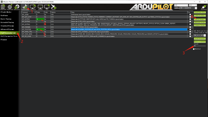
Set the parameters in ArduPilot:
•SERIALx_BAUD = 115
•SERIALx_PROTOCOL = 1
Where “x” is the port number. The value is 1 (Mavlink).
In addition, set the following message rates for this port:
•SRx_EXTRA1 = 10
•SRx_POSITION = 10
Note: All other SRx_xx parameters should be set to 0 to prevent unnecessary data from overloading the channel.
Answer:
(1) Roll axis tilt: Turn off SR1_EXRA3 data
(2) Big delay: Change SRx_RC_CHAN to 20HZ
(3) No respond to FC Mavlink serial port control: The program is older than 20210429. Update.
Case 1: Pixhawk, Pixkack/ V3 FC connect to RSSI, V5 series FC connect to SBUS_out pin
Answer: BRD_SBUS_OUT set to 1 (50hz)
SERVO_SBUS_OUT default as 50
BRD_SAFETYENABLE change default 1 to 0 , or turn on safety button.
Case 2: X7 series FC do not have independent SBUS_OUT interface, output SBUS signal by serial port directly
Answer: SERIAL4_PROTOCOL set to 15
SERIAL4_OPTIONS set to 2
After the above settings, TX pin of FC uart4 interface will output SBUS signal. Similarly, other serial port can also be set as SBUS output.
Control method:
Servo8 set as 56, the channel 6 of the RC controls the channel 8 output by FC, which is to control the channel 8 output by SBUS.
Appendix:
|
SONY 30x Optical Zoom Ratio&Pos |
||||
|
index |
POS hex 0xpqrs |
ZOOM Ratio |
H FOV |
V FOV |
|
0 |
0 |
1.00 |
63.7 |
38.5 |
|
1 |
40 |
1.01 |
63.1 |
38.1 |
|
2 |
80 |
1.01 |
63.1 |
38.1 |
|
3 |
C0 |
1.02 |
62.6 |
37.8 |
|
4 |
100 |
1.03 |
62.1 |
37.4 |
|
5 |
140 |
1.03 |
62.1 |
37.4 |
|
6 |
180 |
1.04 |
61.7 |
37.1 |
|
7 |
1C0 |
1.05 |
61.2 |
36.8 |
|
8 |
200 |
1.05 |
61.2 |
36.8 |
|
9 |
240 |
1.06 |
60.7 |
36.5 |
|
10 |
280 |
1.07 |
60.2 |
36.1 |
|
11 |
2C0 |
1.07 |
60.2 |
36.1 |
|
12 |
300 |
1.08 |
59.8 |
35.8 |
|
13 |
340 |
1.09 |
59.3 |
35.5 |
|
14 |
380 |
1.10 |
58.9 |
35.2 |
|
15 |
3C0 |
1.10 |
58.9 |
35.2 |
|
16 |
400 |
1.11 |
58.4 |
34.9 |
|
17 |
440 |
1.12 |
58.0 |
34.6 |
|
18 |
480 |
1.13 |
57.6 |
34.3 |
|
19 |
4C0 |
1.13 |
57.6 |
34.3 |
|
20 |
500 |
1.14 |
57.1 |
34.1 |
|
21 |
540 |
1.15 |
56.7 |
33.8 |
|
22 |
580 |
1.16 |
56.3 |
33.5 |
|
23 |
5C0 |
1.16 |
56.3 |
33.5 |
|
24 |
600 |
1.17 |
55.9 |
33.2 |
|
25 |
640 |
1.18 |
55.5 |
33.0 |
|
26 |
680 |
1.19 |
55.1 |
32.7 |
|
27 |
6C0 |
1.20 |
54.7 |
32.4 |
|
28 |
700 |
1.21 |
54.3 |
32.2 |
|
29 |
740 |
1.21 |
54.3 |
32.2 |
|
30 |
780 |
1.22 |
53.9 |
31.9 |
|
31 |
7C0 |
1.23 |
53.6 |
31.7 |
|
32 |
800 |
1.24 |
53.2 |
31.4 |
|
33 |
840 |
1.25 |
52.8 |
31.2 |
|
34 |
880 |
1.26 |
52.5 |
31.0 |
|
35 |
8C0 |
1.27 |
52.1 |
30.7 |
|
36 |
900 |
1.28 |
51.7 |
30.5 |
|
37 |
940 |
1.29 |
51.4 |
30.3 |
|
38 |
980 |
1.30 |
51.1 |
30.1 |
|
39 |
9C0 |
1.31 |
50.7 |
29.8 |
|
40 |
A00 |
1.32 |
50.4 |
29.6 |
|
41 |
A40 |
1.33 |
50.0 |
29.4 |
|
42 |
A80 |
1.34 |
49.7 |
29.2 |
|
43 |
AC0 |
1.35 |
49.4 |
29.0 |
|
44 |
B00 |
1.36 |
49.1 |
28.8 |
|
45 |
B40 |
1.37 |
48.8 |
28.6 |
|
46 |
B80 |
1.38 |
48.4 |
28.4 |
|
47 |
BC0 |
1.39 |
48.1 |
28.2 |
|
48 |
C00 |
1.40 |
47.8 |
28.0 |
|
49 |
C40 |
1.41 |
47.5 |
27.8 |
|
50 |
C80 |
1.42 |
47.2 |
27.6 |
|
51 |
CC0 |
1.43 |
46.9 |
27.4 |
|
52 |
D00 |
1.44 |
46.6 |
27.3 |
|
53 |
D40 |
1.45 |
46.4 |
27.1 |
|
54 |
D80 |
1.46 |
46.1 |
26.9 |
|
55 |
DC0 |
1.48 |
45.5 |
26.5 |
|
56 |
E00 |
1.49 |
45.2 |
26.4 |
|
57 |
E40 |
1.50 |
45.0 |
26.2 |
|
58 |
E80 |
1.51 |
44.7 |
26.0 |
|
59 |
EC0 |
1.52 |
44.4 |
25.9 |
|
60 |
F00 |
1.54 |
43.9 |
25.5 |
|
61 |
F40 |
1.55 |
43.7 |
25.4 |
|
62 |
F80 |
1.56 |
43.4 |
25.2 |
|
63 |
FC0 |
1.57 |
43.1 |
25.1 |
|
64 |
1000 |
1.59 |
42.7 |
24.8 |
|
65 |
1040 |
1.60 |
42.4 |
24.6 |
|
66 |
1080 |
1.61 |
42.2 |
24.5 |
|
67 |
10C0 |
1.63 |
41.7 |
24.2 |
|
68 |
1100 |
1.64 |
41.5 |
24.0 |
|
69 |
1140 |
1.65 |
41.2 |
23.9 |
|
70 |
1180 |
1.67 |
40.8 |
23.6 |
|
71 |
11C0 |
1.68 |
40.6 |
23.5 |
|
72 |
1200 |
1.70 |
40.1 |
23.2 |
|
73 |
1240 |
1.71 |
39.9 |
23.1 |
|
74 |
1280 |
1.72 |
39.7 |
22.9 |
|
75 |
12C0 |
1.74 |
39.3 |
22.7 |
|
76 |
1300 |
1.75 |
39.1 |
22.6 |
|
77 |
1340 |
1.77 |
38.7 |
22.3 |
|
78 |
1380 |
1.79 |
38.3 |
22.1 |
|
79 |
13C0 |
1.80 |
38.1 |
21.9 |
|
80 |
1400 |
1.82 |
37.7 |
21.7 |
|
81 |
1440 |
1.83 |
37.5 |
21.6 |
|
82 |
1480 |
1.85 |
37.1 |
21.4 |
|
83 |
14C0 |
1.87 |
36.7 |
21.1 |
|
84 |
1500 |
1.88 |
36.5 |
21.0 |
|
85 |
1540 |
1.90 |
36.2 |
20.8 |
|
86 |
1580 |
1.92 |
35.8 |
20.6 |
|
87 |
15C0 |
1.94 |
35.5 |
20.4 |
|
88 |
1600 |
1.95 |
35.3 |
20.3 |
|
89 |
1640 |
1.97 |
35.0 |
20.1 |
|
90 |
1680 |
1.99 |
34.6 |
19.9 |
|
91 |
16C0 |
2.01 |
34.3 |
19.7 |
|
92 |
1700 |
2.03 |
34.0 |
19.5 |
|
93 |
1740 |
2.05 |
33.7 |
19.3 |
|
94 |
1780 |
2.07 |
33.4 |
19.1 |
|
95 |
17C0 |
2.09 |
33.1 |
19.0 |
|
96 |
1800 |
2.11 |
32.8 |
18.8 |
|
97 |
1840 |
2.13 |
32.5 |
18.6 |
|
98 |
1880 |
2.15 |
32.2 |
18.4 |
|
99 |
18C0 |
2.17 |
31.9 |
18.3 |
|
100 |
1900 |
2.19 |
31.6 |
18.1 |
|
101 |
1940 |
2.21 |
31.4 |
17.9 |
|
102 |
1980 |
2.23 |
31.1 |
17.8 |
|
103 |
19C0 |
2.26 |
30.7 |
17.5 |
|
104 |
1A00 |
2.28 |
30.5 |
17.4 |
|
105 |
1A40 |
2.30 |
30.2 |
17.2 |
|
106 |
1A80 |
2.32 |
29.9 |
17.1 |
|
107 |
1AC0 |
2.35 |
29.6 |
16.9 |
|
108 |
1B00 |
2.37 |
29.3 |
16.7 |
|
109 |
1B40 |
2.40 |
29.0 |
16.5 |
|
110 |
1B80 |
2.42 |
28.8 |
16.4 |
|
111 |
1BC0 |
2.45 |
28.4 |
16.2 |
|
112 |
1C00 |
2.47 |
28.2 |
16.1 |
|
113 |
1C40 |
2.50 |
27.9 |
15.9 |
|
114 |
1C80 |
2.53 |
27.6 |
15.7 |
|
115 |
1CC0 |
2.55 |
27.3 |
15.6 |
|
116 |
1D00 |
2.58 |
27.0 |
15.4 |
|
117 |
1D40 |
2.61 |
26.7 |
15.2 |
|
118 |
1D80 |
2.64 |
26.4 |
15.0 |
|
119 |
1DC0 |
2.66 |
26.3 |
14.9 |
|
120 |
1E00 |
2.69 |
26.0 |
14.8 |
|
121 |
1E40 |
2.72 |
25.7 |
14.6 |
|
122 |
1E80 |
2.75 |
25.4 |
14.4 |
|
123 |
1EC0 |
2.78 |
25.2 |
14.3 |
|
124 |
1F00 |
2.82 |
24.8 |
14.1 |
|
125 |
1F40 |
2.85 |
24.6 |
13.9 |
|
126 |
1F80 |
2.88 |
24.3 |
13.8 |
|
127 |
1FC0 |
2.91 |
24.1 |
13.7 |
|
128 |
2000 |
2.95 |
23.7 |
13.5 |
|
129 |
2040 |
2.98 |
23.5 |
13.3 |
|
130 |
2080 |
3.02 |
23.2 |
13.2 |
|
131 |
20C0 |
3.05 |
23.0 |
13.0 |
|
132 |
2100 |
3.09 |
22.7 |
12.9 |
|
133 |
2140 |
3.12 |
22.5 |
12.7 |
|
134 |
2180 |
3.16 |
22.2 |
12.6 |
|
135 |
21C0 |
3.20 |
21.9 |
12.4 |
|
136 |
2200 |
3.24 |
21.7 |
12.3 |
|
137 |
2240 |
3.28 |
21.4 |
12.1 |
|
138 |
2280 |
3.32 |
21.2 |
12.0 |
|
139 |
22C0 |
3.36 |
20.9 |
11.8 |
|
140 |
2300 |
3.40 |
20.7 |
11.7 |
|
141 |
2340 |
3.44 |
20.4 |
11.6 |
|
142 |
2380 |
3.49 |
20.1 |
11.4 |
|
143 |
23C0 |
3.53 |
19.9 |
11.3 |
|
144 |
2400 |
3.57 |
19.7 |
11.1 |
|
145 |
2440 |
3.62 |
19.4 |
11.0 |
|
146 |
2480 |
3.67 |
19.2 |
10.8 |
|
147 |
24C0 |
3.71 |
19.0 |
10.7 |
|
148 |
2500 |
3.76 |
18.7 |
10.6 |
|
149 |
2540 |
3.81 |
18.5 |
10.4 |
|
150 |
2580 |
3.86 |
18.2 |
10.3 |
|
151 |
25C0 |
3.91 |
18.0 |
10.2 |
|
152 |
2600 |
3.97 |
17.7 |
10.0 |
|
153 |
2640 |
4.02 |
17.5 |
9.9 |
|
154 |
2680 |
4.07 |
17.3 |
9.8 |
|
155 |
26C0 |
4.13 |
17.1 |
9.6 |
|
156 |
2700 |
4.19 |
16.8 |
9.5 |
|
157 |
2740 |
4.24 |
16.6 |
9.4 |
|
158 |
2780 |
4.30 |
16.4 |
9.3 |
|
159 |
27C0 |
4.36 |
16.2 |
9.1 |
|
160 |
2800 |
4.43 |
15.9 |
9.0 |
|
161 |
2840 |
4.49 |
15.7 |
8.9 |
|
162 |
2880 |
4.55 |
15.5 |
8.7 |
|
163 |
28C0 |
4.62 |
15.3 |
8.6 |
|
164 |
2900 |
4.68 |
15.1 |
8.5 |
|
165 |
2940 |
4.75 |
14.9 |
8.4 |
|
166 |
2980 |
4.82 |
14.6 |
8.3 |
|
167 |
29C0 |
4.89 |
14.4 |
8.1 |
|
168 |
2A00 |
4.97 |
14.2 |
8.0 |
|
169 |
2A40 |
5.04 |
14.0 |
7.9 |
|
170 |
2A80 |
5.12 |
13.8 |
7.8 |
|
171 |
2AC0 |
5.19 |
13.6 |
7.7 |
|
172 |
2B00 |
5.27 |
13.4 |
7.5 |
|
173 |
2B40 |
5.35 |
13.2 |
7.4 |
|
174 |
2B80 |
5.44 |
13.0 |
7.3 |
|
175 |
2BC0 |
5.52 |
12.8 |
7.2 |
|
176 |
2C00 |
5.61 |
12.6 |
7.1 |
|
177 |
2C40 |
5.69 |
12.4 |
7.0 |
|
178 |
2C80 |
5.78 |
12.2 |
6.9 |
|
179 |
2CC0 |
5.88 |
12.0 |
6.8 |
|
180 |
2D00 |
5.97 |
11.8 |
6.7 |
|
181 |
2D40 |
6.07 |
11.6 |
6.5 |
|
182 |
2D80 |
6.17 |
11.4 |
6.4 |
|
183 |
2DC0 |
6.27 |
11.3 |
6.3 |
|
184 |
2E00 |
6.37 |
11.1 |
6.2 |
|
185 |
2E40 |
6.47 |
10.9 |
6.1 |
|
186 |
2E80 |
6.58 |
10.7 |
6.0 |
|
187 |
2EC0 |
6.69 |
10.6 |
5.9 |
|
188 |
2F00 |
6.80 |
10.4 |
5.8 |
|
189 |
2F40 |
6.92 |
10.2 |
5.7 |
|
190 |
2F80 |
7.03 |
10.0 |
5.7 |
|
191 |
2FC0 |
7.15 |
9.9 |
5.6 |
|
192 |
3000 |
7.28 |
9.7 |
5.5 |
|
193 |
3040 |
7.40 |
9.5 |
5.4 |
|
194 |
3080 |
7.53 |
9.4 |
5.3 |
|
195 |
30C0 |
7.66 |
9.2 |
5.2 |
|
196 |
3100 |
7.79 |
9.1 |
5.1 |
|
197 |
3140 |
7.93 |
8.9 |
5.0 |
|
198 |
3180 |
8.07 |
8.7 |
4.9 |
|
199 |
31C0 |
8.21 |
8.6 |
4.8 |
|
200 |
3200 |
8.35 |
8.4 |
4.8 |
|
201 |
3240 |
8.50 |
8.3 |
4.7 |
|
202 |
3280 |
8.65 |
8.2 |
4.6 |
|
203 |
32C0 |
8.81 |
8.0 |
4.5 |
|
204 |
3300 |
8.97 |
7.9 |
4.4 |
|
205 |
3340 |
9.13 |
7.7 |
4.3 |
|
206 |
3380 |
9.29 |
7.6 |
4.3 |
|
207 |
33C0 |
9.46 |
7.5 |
4.2 |
|
208 |
3400 |
9.63 |
7.3 |
4.1 |
|
209 |
3440 |
9.80 |
7.2 |
4.0 |
|
210 |
3480 |
9.98 |
7.1 |
4.0 |
|
211 |
34C0 |
10.16 |
6.9 |
3.9 |
|
212 |
3500 |
10.35 |
6.8 |
3.8 |
|
213 |
3540 |
10.54 |
6.7 |
3.8 |
|
214 |
3580 |
10.73 |
6.6 |
3.7 |
|
215 |
35C0 |
10.93 |
6.4 |
3.6 |
|
216 |
3600 |
11.13 |
6.3 |
3.6 |
|
217 |
3640 |
11.33 |
6.2 |
3.5 |
|
218 |
3680 |
11.54 |
6.1 |
3.4 |
|
219 |
36C0 |
11.75 |
6.0 |
3.4 |
|
220 |
3700 |
11.97 |
5.9 |
3.3 |
|
221 |
3740 |
12.19 |
5.8 |
3.2 |
|
222 |
3780 |
12.41 |
5.7 |
3.2 |
|
223 |
37C0 |
12.64 |
5.6 |
3.1 |
|
224 |
3800 |
12.88 |
5.5 |
3.1 |
|
225 |
3840 |
13.12 |
5.4 |
3.0 |
|
226 |
3880 |
13.36 |
5.3 |
3.0 |
|
227 |
38C0 |
13.61 |
5.2 |
2.9 |
|
228 |
3900 |
13.87 |
5.1 |
2.8 |
|
229 |
3940 |
14.13 |
5.0 |
2.8 |
|
230 |
3980 |
14.40 |
4.9 |
2.7 |
|
231 |
39C0 |
14.67 |
4.8 |
2.7 |
|
232 |
3A00 |
14.95 |
4.7 |
2.6 |
|
233 |
3A40 |
15.24 |
4.6 |
2.6 |
|
234 |
3A80 |
15.54 |
4.5 |
2.5 |
|
235 |
3AC0 |
15.85 |
4.4 |
2.5 |
|
236 |
3B00 |
16.17 |
4.3 |
2.4 |
|
237 |
3B40 |
16.50 |
4.2 |
2.4 |
|
238 |
3B80 |
16.84 |
4.2 |
2.3 |
|
239 |
3BC0 |
17.20 |
4.1 |
2.3 |
|
240 |
3C00 |
17.57 |
4.0 |
2.2 |
|
241 |
3C40 |
17.96 |
3.9 |
2.2 |
|
242 |
3C80 |
18.36 |
3.8 |
2.1 |
|
243 |
3CC0 |
18.79 |
3.7 |
2.1 |
|
244 |
3D00 |
19.25 |
3.6 |
2.0 |
|
245 |
3D40 |
19.73 |
3.5 |
2.0 |
|
246 |
3D80 |
20.25 |
3.4 |
1.9 |
|
247 |
3DC0 |
20.81 |
3.3 |
1.9 |
|
248 |
3E00 |
21.41 |
3.3 |
1.8 |
|
249 |
3E40 |
22.07 |
3.2 |
1.8 |
|
250 |
3E80 |
22.80 |
3.1 |
1.7 |
|
251 |
3EC0 |
23.60 |
2.9 |
1.7 |
|
252 |
3F00 |
24.51 |
2.8 |
1.6 |
|
253 |
3F40 |
25.55 |
2.7 |
1.5 |
|
254 |
3F80 |
26.76 |
2.6 |
1.5 |
|
255 |
3FC0 |
28.21 |
2.5 |
1.4 |
|
256 |
4000 |
30.00 |
2.3 |
1.3 |